More Rinnai tankless hot water heater error codes Ontario Canada.
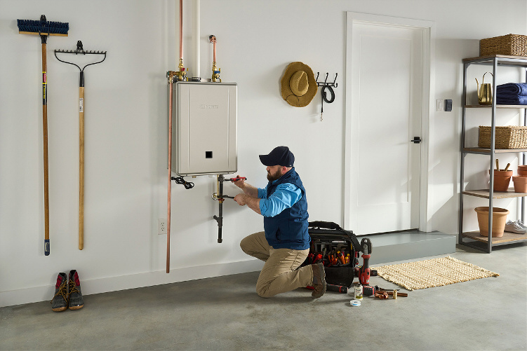
Tankless water heater service and repair. Call 647 931-5211
Non-SENSEI™ Series
Only trained and qualified professionals are permitted to follow the instructions in this document.
• If the information in these instructions is not followed exactly, a fire or explosion may result causing
property damage, personal injury, or death.
• Before operating, smell all around the water heater area for gas. Be sure to smell next to the floor because
some gas is heavier than air and will settle on the floor. WHAT TO DO IF YOU SMELL GAS:
− Do not try to light any water heater.
− Do not touch any electrical switch; do not use any phone in your building.
− Immediately call your gas supplier from a neighbor’s phone. Follow the gas supplier’s instructions.
− If you cannot reach your gas supplier, call the fire department.
• Before diagnosing and servicing the tankless water heater, turn off the electrical power supply, gas and
incoming water supply.
• Before checking resistance readings, unplug the water heater and then isolate each item to be checked from
the circuit.
• DO NOT adjust the internal gas valve. The design is such that adjustment is not required. Warranty will be
voided if the internal gas valve is adjusted.
• Keep the area around the water heater clear and free from combustible materials, gasoline, and other
flammable vapors and liquids. Flammable liquids such as cleaning solvents, aerosols, paint thinners,
adhesives, gasoline and propane must be handled and stored with extreme care. These flammable liquids
emit flammable vapors and when exposed to an ignition source can result in a fire hazard or explosion.
Flammable liquids should not be used or stored in the vicinity of this or any other gas water heater.
• There are numerous live tests required when troubleshooting tankless water heaters. Use extreme care to
avoid contact with energized components inside the tankless water heater.
• Label all wires prior to disconnection when servicing controls. Wiring errors may cause improper and
dangerous operation.
• Do not use this water heater if any part has been under water.
• Do not use substitute materials. Use only parts certified for the water heater.
• Do not use an extension cord or adapter plug with this water heater.
• Any alteration to the water heater or its controls can be dangerous and will void the warranty.
• DO NOT operate the water heater without the front panel installed. The front panel should only be removed
for service/maintenance or replacing internal components.
• BURN HAZARD. Hot exhaust and vent may cause serious burns. Keep away from the water heater. Keep
small children and animals away from the water heater.
• Hot water outlet pipes leaving the water heater can be hot to touch.
Value VC
V53e REU-VAM1620W-US
V53De REU-AM1620WD-US
V65i REU-VC2025FFU-US
V65e REU-VC2025W-US
V75i REU-VC2528FFU-US
V75e REU-VC2528W-US
V94i REU-VC2837FFU-US
V94Xi REU-VC2737FFU-US
V94e REU-VC2837W-US
Luxury VC
RL75i REU-VC2528FFUD-US
RL75i(A) REU-VC2528FFUD-US(A)
RL75e REU-VC2528WD-US
RL75e(A) REU-VC2528WD-US(A)
RL94i REU-VC2837FFUD-US
RLX94i REU-VC2737FFUD-US
RL94e REU-VC2837WD-US
KCM
RUCS65i REU-KCM2025FFU-US
RUCS75i REU-KCM2528FFU-US
RUS65e REU-KCM2025W-US
RUS75e REU-KCM2528W-US
KBD
RUC80i REU-KBD2530FFUD-US
RUC90i REU-KBD2934FFUD-US
RUC98i REU-KBD3237FFUD-US
KB
RU80i REU-KB2530FFUD-US
RU80e REU-KB2530WD-US
RU90e REU-KBD2934WD-US
RU98i REU-KB3237FFUD-US
RU98e REU-KB3237WD-US
KBP
RUR98i REU-KBP3237FFUD-US
RUR98e REU-KBP3237WD-US
Commercial
C199i REU-KBD3237FFUDC-US
C199e REU-KB3237WDC-US
HTT (Hybrid Tank-Tankless)
RH180 REU-VA1320WF-US
RU199i REU-N3237FF-US
RU180i REU-N2934FF-US
RU160i REU-N2530FF-US
RU130i REU-N2024FF-US
RU199e REU-N3237W-US
RU180e REU-N2934W-US
RU160e REU-N2530W-US
RU130e REU-N2024W-US
SENSEI™ Residential with Pump
RUR199i REU-NP3237FF-US
RUR160i REU-NP2530FF-US
RUR199e REU-NP3237W-US
RUR160e REU-NP2530W-US
SENSEI™ Commercial
CU199i REU-N3237FFC-US
CU160i REU-N2530FFC-US
CU199e REU-N3237WC-US
CU160e REU-N2530WC-US
1. Verify all gas valves are open and feeding the proper gas pressure to water heater.
2. Verify all air was properly purged from gas lines after installation.
3. Verify proper inlet gas pressure is being fed to the water heater (check water heater’s rating plate for proper
pressures, which is located on side of water heater). The minimum listed inlet pressure MUST be maintained with
all gas water heaters at the location firing on high fire. If water heater is a condensing water heater, the front
panel must be installed before testing inlet pressures.
4. Verify proper gas type (ensure gas supply at location matches gas supply listed on water heater).
5. Verify gas type DIP switch on PC Board is set to proper gas type position.
Turn off gas valve feeding water heater before proceeding with the next step.
6. Verify igniter is working. Unplug igniter wire. Hold the igniter wire with an insulated pair of pliers about a 1/4 in.
from a metal item on the water heater. Cycle the water heater (initiate hot water flow to initiate ignition cycle) to
ensure you see a spark between the tip of the igniter wire and metal item on the water heater. If a spark is not
observed, check ignition system for loose connections, damaged components or disconnected plugs back to PC
Board. Also, check the ignition board to verify it is getting the proper voltage from the PC Board (refer to Technical
Data Sheet on inside of water heater front cover for proper voltage and connector numbers). Note: There will be
no voltage present unless the water heater is going through the ignition cycle.
7. Confirm the ceramic sparker electrode and flame rod(s) are tight in the mounting bracket. You should not be able
to move the flame rod(s) or electrode with your finger if gasket is intact. If loose, remove and clean the electrode
and flame rod(s). Then, reinstall using new electrode/flame rod gasket. Ensure the components are tight when
gasket has been replaced. Loose flame rod(s) or electrodes can lead to a code 11 or 12.
8. Verify the proper flame rod wire is plugged into the proper flame rod. Some water heaters have multiple flame
rods. A quick check to verify correct wiring is to look at the stamped letter on the bracket at flame rod (Y=Yellow,
R=Red, B=Blue).
9. Look into view window on water heater. Do you see a flame in the burner box while the water heater is going
through the ignition cycle? If you do see a flame, then there is an issue in the flame rectification circuit. This could
be a buildup of carbon or a white substance on flame rod, bad connection at flame rod, loose or damaged flame
rod, bad PC Board, gas valve, or low inlet gas pressures. Before replacing the PC Board or gas valve, continue
following the steps below.
WARNING Turn off electrical, gas and water supply before performing this inspection.
10. Remove the igniter and flame rod assemblies and inspect for carbon or white substance build-up. Note: The
electrode packing must be replaced if damaged. Have a new electrode packing available before removal of the
flame rod assembly. Clean the igniter and flame rod and then re-install them.
Troubleshooting Tankless Water Heater Diagnostic Codes 5
CAUTION
WARNING Turn off electrical, gas and water supply to the water heater before proceeding with the step
below.
11. Remove burner manifold and inspect orifices on back side of manifold for clogged or blocked orifices. Remove
burner assembly and inspect chamber for insects or other debris. Clean out all debris found in burner and air chambers. Inspect copper fins in heat exchanger for a build-up between fins. Build-up or blockage between heat exchanger fins causes air flow restrictions, which will lead to a code 10. If build-up is present, you need an air compressor capable of delivering 120 psi of compressed air to blow out burner and heat exchanger fins. If unable to
clean the heat exchanger with compressed air, replace heat exchanger.
Always wear safety glasses and a mask when blowing out the burner.
12. If you note improper inlet gas pressures, check if the gas system was properly sized. If sized properly, you should
see no more than a 0.3 in. pressure drop on natural gas with all gas water heaters in the building firing on high fire.
The allowable pressure drop for Propane is 0.5 in. of water column. This pressure drop is based on the International Plumbing Code when operating on gas pressures up to 14 in. W.C. with black iron piping. There are numerous
gas piping systems approved in the market. Make sure you refer to the manufacturer or International Plumbing
Code manual for pressure drops on gas piping and pressures you are using for proper pressure drops allowed. If
pressure drop exceeds that mentioned above for black iron gas systems, your system could be undersized (please
recheck sizing). The issue could be in any of the following items: gas system, gas piping, regulator, tank, utility supply, dirt or debris in gas system components, etc. Have the gas system checked by a professional gas technician or
master plumber that specializes in gas system sizing. Refer to the International Plumbing Code manual for proper
gas system sizing for gas type, piping and pressures being used at this location.
13. Inspect vent system for loose joints, improper fittings, or failure to meet clearances around vent terminal outside
building (see venting instructions for clearance specifications). Failure to meet vent terminal clearances can lead to
recirculation of combustion gases on all water heaters (with exception of the RH-180 tankless water heater), causing incomplete combustion (which leads to carbon build-up on the flame rod). Ensure vent length is within specifications and DIP switches for vent lengths have been properly set.
14. Verify proper venting materials were used in this installation (refer to Tankless Water Heater Installation and Operation Manual or venting instructions for the proper type venting materials that should be used with your water
heater).
15. Verify proper altitude settings (refer to high altitude gas pressure setting procedure for DIP switches and manifold
gas pressure settings found in Tankless Water Heater Installation and Operation Manual or Technical Data Sheet on
inside of water heater front cover for proper altitude settings).
16. On internal water heaters, inspect the plastic tube running from the bottom of the combustion chamber to the gas
valve. If you find moisture in the tube, replace the gas valve. Inspect the vent system to detect where the condensate/moisture is coming from. Inspect the burner and heat exchanger fins for excessive corrosion. Signs of moisture could be a result of improper venting or a leak inside the heat exchanger.
17. Verify the condensate drain trap was used as recommended by Rinnai on non-condensing water heaters at the
vent terminal connection at the top of the water heaters (with exception to the RH-180). If the condensate drain
line is not connected, please install one per Rinnai venting instructions. If a condensate line is in use, inspect the
vent connector on top of water heater to ensure it is not clogged up. In addition, check the condensate drain trap
and line for blockage. If stopped up, remove vent pipe from water heater and clean out all debris and/or build-up
from the trap or line.
18. Check that any two stage regulator used on the inlet gas feed is installed at least six feet away from water heater.
Ensure when water heater shuts off, the pressure from the two stage regulator does not exceed the maximum inlet
pressure of the water heater (no bleed-though being allowed). To verify, connect a manometer up to the test port on
the bottom of the water heater. The inlet gas pressures should never exceed 10 in. water column for natural gas or
13.5 in. on propane; if the inlet gas pressures exceed these numbers, then the regulator may be defective.
Disconnect power supply to water heater before performing the following step.
WARNING
19. Inspect all wiring harnesses throughout water heater for water or moisture in electrical connections. If any
connections appear damp or wet, then dry them out and find out the cause.
20. If using an MSA or MSB system, isolate the water heater displaying the diagnostic code from the system during
troubleshooting. If water heater operates when isolated, the issue may be in the electronic staging system (MSA
or MSB). The MSA or MSB system does not apply to the RH-180.
For VA, VB, VC, KA, RH-180 and KCM Water Heaters: Turn off electrical, gas and water supply
to the water heater before proceeding with the step below.
21. Other suggestions to try
• Verify spark electrode is installed in the correct position.
• Verify all burner cassettes are in place in burner rack. If a water heater is dropped, the burners may shift and
dislodge; if dislodged, loosen the burner bracket and reseat the burners.
• Remove the four burners located under the flame rod and move them over to the high fire side of the burner
tray. Move the four burners from the high fire side over under the flame rod. Sometimes condensate or debris
can be inside the burners and cause turbulence inside the burner.
• Condensate, debris or a malfunctioning mechanical component inside the gas valve may prevent the valve
from opening correctly. Replace gas valve.
• Voltage output to gas valve from PC Board could be incorrect or intermittent due to a defective component on
PC Board. Replace PC Board.
Error codes 3
Applies To:
• SENSEI™ Series
• Non-SENSEI™ Serie
1. Turn off all hot water fixtures.
2. Press ON/OFF button on controller twice; this resets the diagnostic code.
3. If the code reappears after resetting the water heater three times, replace the PC Board
Error codes 5
Applies To:
• SENSEI™ Series
• Non-SENSEI™ Series
• RH180 (Hybrid Tank-Tankless Non-SENSEI™ Series Water Heater)
SENSEI™ Series
1. Measure resistance values of Bypass Flow Control Device at connector on PC Board (refer to “Electric Circuit Table”
in Tech Sheet and Wiring Diagram for further clarification).
• Connector “D” red wire pin #15 and pink wire pin #13 – 44 ~ 52Ω.
• Connector “D” white wire pin #17 and blue wire pin #19 – 44 ~ 52Ω.
Non sensei series
2. Replace bypass flow control device.
1. Turn off power supply to water heater and then reapply power.
2. Turn on a hot water fixture and let water heater activate. If Code 05 reappears, replace the bypass valve.
RH 180 models.
1. Clean air filter.
2. Ensure proper vent system and components were installed per Rinnai’s recommended installation instructions
(located in Tankless Water Heater Installation and Operation Manual). Approved vent material is 4 in. B-Vent.
3. Inspect vent system for obstructions.
4. Verify proper clearance is maintained around vent termination.
5. Remove fan motor and inspect fan wheel and housing for any type of restriction. Re-install fan. Turn on power to
water heater and test for proper operation.
6. Remove burner manifold and inspect orifices on back side of manifold for clogged or blocked orifices.
7. Remove burner assembly and inspect chamber for insects or other debris. Clean out all debris found in burner and
air chambers.
8. Inspect copper fins in heat exchanger for a build-up between the fins. Build-up or blockage between heat
exchanger fins will cause air flow restrictions, which will lead to code 05 or 10. If build-up is present, blow out
burner and heat exchanger fins with an air compressor capable of delivering 120 PSI of compressed air. If unable to
clean heat exchanger with compressed air, replace heat exchanger.
9. If the above steps do not clear Code 05, proceed to Code 10 troubleshooting steps.
Code 07
Circucirculation flow rate below 2.1 GPM ( Gallons per Minute )
Applies To:
• RH180 (Hybrid Tank-Tankless Non-SENSEI™ Series Water Heater)
1. Verify water heater has power.
2. Verify water supply is turned on and the supply pressure is at least 30 PSI.
3. Check to see if pump is operational.
4. Check pump wiring harness for loose, damaged or broken connections.
5. Drain tank. Clean inlet water filter.
6. Flush heat exchanger to ensure it is not clogged with scale build-up. Follow the flushing procedure as outlined in
the Rinnai Tankless Water Heater Installation and Operation Manual.
Code 10
Air supply , exhaust blockage or condensate trap is full.
Applies To:
• SENSEI™ Series
• Non-SENSEI™ Series
1. Check to ensure the condensate line is properly draining. If the condensate drain line becomes clogged or freezes
up, it will back up into the condensate trap inside the water heater, shutting the water heater off to prevent spillage and setting off a code 10. If the condensate line is properly draining, proceed to the next step.
2. Clean inlet air filter under front cover in top right of water heater cabinet.
3. Inspect the entire intake and exhaust piping system inside/outside the installation site. Check for clearance issues,
ensure the proper venting materials were used and all vent component sections are properly seated and cut to
vent supplier’s recommendations.
Note: Rinnai offers numerous types of venting materials. You must ensure the proper vent materials are used on
the water heater. Refer to the owner’s manual of the product being serviced for the approved venting materials
allowed for your specific water heater.
WARNING Never leave a water heater operating with the vent system (intake or exhaust) piping
disconnected. The following procedure is only a test. Reconnect the vent system immediately
after performing this test.
4. The following test can be performed only if the water heater is coding out while onsite. Remove the exhaust section of the vent system from the top of the water heater. Turn on a hot water fixture to see if the water heater will
activate without coding out. If so, this indicates a restriction in the vent system’s intake or exhaust piping.
5. If the water heater codes out during the above test, proceed as follows: Disassemble each section of vent pipe to
inspect it for proper installation and vent component insertion depth. To confirm proper installation, mark each
vent component with a marker before disassembling it. By marking the sections, you can now determine the depth
of each joint after you pull it apart. Make sure to use a lubricant supplied by vent supplier when assembling the
vent sections.
WARNING Failure to use the vent supplier’s lubricant may result in cross contamination during
combustion. Bad connections may cause noise during combustion, exhaust gas leakage and a
code 10.
6. Verify the vent system being used is within the allowable equivalent vent length. See the Tankless Water Heater
Installation and Operation Manual or vent system installation manual to determine the proper equivalent vent
lengths and number of elbows allowed. For example, a vent system using Rinnai’s concentric venting materials with
two ninety-degree elbows, two forty-five degree elbows, and ten feet of straight pipe would be calculated out to
28 equivalent feet. When using Rinnai’s concentric venting, the 90-degree elbow counts as six feet of vent pipe and
each 45 degree counts as three feet of vent pipe.
7. If installer sprayed a foam sealant around the vent pipe penetration through the wall, check to ensure this material
did not collapse the vent pipe penetration. Look down the vent pipe with a flashlight or camera to verify the piping
has not collapsed. If you cannot see that section of venting material, remove it from the wall to inspect it.
Troubleshooting Tankless Water Heater Diagnostic Codes 11
14. Remove the heat exchanger assembly from the water heater. Separate the burner assembly from the heat exchanger assembly and inspect the burner chamber for insects or other debris. Clean out all debris found in the
burner and air chamber cavity. Pull the burner completely out of the housing to inspect the back side of it for
blockage. DO NOT blow burner out with compressed air, as it could damage the burner.
15. While the heat exchanger is out of the water heater, inspect fins around the water flow passage tubes inside the
primary and secondary heat exchangers for debris build-up and/or blockage. If build-up is present, blow heat exchanger out with 120 psi of compressed air to clear any air restrictions. If unable to clean out debris, replace the
heat exchangers.
1. Inspect the entire vent system inside/outside the installation site. Check for clearance issues, ensure proper
venting materials were used, ensure all sections are properly seated, joints are sealed and cannot be pulled apart,
etc.
Note: Rinnai offers numerous types of venting materials. You must ensure the proper vent materials are used on
the water heater. Refer to the owner’s manual of the product being serviced for the approved venting materials
allowed for your specific water heater.
WARNING Failure to use the lubricant may result in improperly sealed joints, which will lead to
a code 10 or exhaust gas leakage.
• Using concentric or common vent materials may require disassembling each section of venting to inspect for
proper installation and depth. Mark each concentric or common vent joint with a marker before
disassembling. This will allow you to determine the proper depth when the vent sections are disassembled.
Make sure to use the lubricant supplied by Rinnai when assembling the concentric or common vent sections.
• Rinnai/Ubbink concentric venting with an aluminum inner pipe and white PVC outer shell for the intake air is
approved for use with all Rinnai Non-condensing tankless water heaters with exception to the RH-180 (see
below for approved venting for the RH-180 water heaters).
• Rinnai/Ubbink concentric venting with a Polypropylene (PP) inner pipe and common vent pipe are approved
for use with all Rinnai Condensing water heaters. The exhaust portion of the system is a special material
made from Polypropylene (PP) piping.
• PVC/CPVC solid core piping can be used to vent Rinnai Condensing tankless water heaters. Ensure all joints
were properly glued and seated. Inspect system for damage, cracked or melted sections.
• Only 4 in. B-Vent venting materials are approved for the RH-180 tank/tankless water heater. Follow vent
manufacturer’s instructions to ensure proper installation of the vent system.
2. Perform this test only if the water heater is coding out while onsite. Remove the vent system from the top of the
water heater. Activate the water heater and see if it will operate without the vent system connected. If so, this is
an indication the issue is in the vent system and not the water heater.
3. Verify DIP switches for vent lengths were set to the proper position. First, determine total vent length. See the
Rinnai Tankless Water Heater Installation and Operation Manual to determine the length of any 90-degree elbows
or 45-degree elbows being used in the vent system. For example, a vent system using concentric venting materials
with two ninety-degree elbows, one forty-five degree elbow, and ten feet of straight pipe would be calculated as
twenty-five feet of total vent length. In concentric venting, a 90-degree elbow counts as six feet. A 45-degree
elbow is three feet.
4. If installer sprayed a foam sealant around the vent pipe penetration through the wall, check to ensure this
material did not collapse the vent pipe penetration. Look down vent pipe with a flash light. If you cannot see that
section of venting material, remove it from the wall and inspect it.
10. Verify the manifold gas pressures and DIP switches were properly set for your altitude.
WARNING For VA, VB, VC, KA, RH-180 and KCM Water Heaters: Turn off electrical, gas and water supply
to the water heater before proceeding with the step below.
11. Other items that may cause a code 10:
• Defective fan motor bearing
• Defective wiring harness to fan motor from PC Board
• Defective PC Board
• Improper DIP switch settings
Code 11
No Ignition
Senseei series
1. Verify all gas valves on the system are open.
2. If the system is propane gas, make sure you have gas in the tank and the tank was properly sized for the
application.
3. Verify all air was purged from gas lines after installation.
4. Verify proper inlet gas pressure is being fed to the water heater (check water heater’s rating plate for proper
pressures, which is located on side of water heater). The minimum listed inlet pressure MUST be maintained with
all gas water heaters at the location firing on high fire.
5. Verify proper gas type (ensure gas supply at location matches gas supply listed on water heater).
6. Verify the gas type at Parameter 10 was properly selected:
• Parameter 10 selection A = Natural Gas
• Parameter 10 selection B = Propane Gas
7. Verify igniter is working. Unplug igniter wire. Hold the igniter wire with an insulated pair of pliers about a 1/4 in.
from a metal item on the water heater. Cycle the water heater (initiate hot water flow to initiate ignition cycle) to
ensure you see a spark between the tip of the igniter wire and metal item on the water heater. If a spark is not
observed, check ignition system for loose connections, damaged components or disconnected plugs back to PC
Board. Also, check the ignition board to verify it is getting the proper voltage from the PC Board (refer to Technical
Data Sheet on inside of water heater front cover for proper voltage and connector numbers).
Measure resistance or voltage of spark electrode on the PC Board at Connector D:
• Connector “D” Black wire pin #21 and Red wire pin #12 = 11 ~ 13 VDC during ignition cycle
• Verify spark electrode gap is 0.138 in. or 3.5 mm
8. Make sure the ceramic sparker electrode and flame rod are tight in the mounting bracket. You should not be able
to move either component with your finger if gasket is intact. If loose, remove and clean the electrode/flame rod.
Reinstall using new electrode/flame rod gasket.
9. Visually inspect the burner flame through the view glass. If you see a flame in the burner box while the water
heater is cycling, the water heater should continue to operate. If the flame goes out, there is an issue with the
flame rectification circuit or gas system. The issue could be a buildup of carbon or a white substance on flame rod,
bad connection at flame rod, loose or damaged flame rod, bad PC Board, defective gas valve or low inlet gas
pressures. Before replacing the PC Board or gas valve, continue troubleshooting the steps below.
10. Remove the igniter and flame rod assemblies and inspect them for carbon or a white substance build-up. Make
sure you have a replacement igniter/flame rod gasket before removing these components. The gasket MUST be
replaced if the seal is broken.
11. Check to ensure the inlet gas pressure is within specifications with all gas water heaters at the location firing on
high fire. If the inlet pressure drops below the allowable inlet pressure, the issue may be caused by one of the
following: gas system, gas piping, regulator, or tank was not properly sized or is defective. You may have dirt or
debris in gas system or components causing issues with the gas supply feed, etc. Have the gas system checked by a
professional gas technician that specializes in gas system sizing and troubleshooting. If sizing is questionable, refer
to the International Plumbing Code Book for proper gas system sizing for gas type, piping and pressures being used
at this location.
12. Inspect vent system for loose connections or joints, improper fittings, failure to meet clearances around vent
terminal outside building, etc. See venting instructions for clearance specifications for the vent system being used.
Failure to meet vent terminal clearances will lead to recirculation of combustion gases causing incomplete
combustion.
13. Ensure the equivalent vent length is within manufacturer’s specifications.
14. Verify that proper venting materials were used with this installation (see the Rinnai Tankless Water Heater
Installation and Operation Manual or venting instructions for details on the proper type venting materials to use
with your water heater)
15. Verify the High Altitude Parameter 02 was properly selected:
• Parameter 02 selection A = 0 – 2,000 ft. (0 – 610 M)
• Parameter 02 selection B = 2,001 – 5.400 ft. (610 – 1,646 M)
• Parameter 02 selection C = 5,401 – 7,700 ft. (1,646 – 2,347 M)
• Parameter 02 selection D = 7,701 – 10,200 ft. (2,347 – 3,109 M)
16. Check for leaks, a common indicator that the heat exchanger is leaking (if liquid is coming out of the condensate
drain and the water heater is not operating).
17. Ensure the two stage regulator used on the inlet gas supply is at least six feet from the inlet gas supply to the water
heater. Make sure when water heater shuts off, the pressure from the two stage regulator does not exceed the
maximum inlet pressure of the water heater and that you have no bleed-though. To verify this, connect a
manometer up to the test port on the bottom of the water heater. The inlet gas pressure should never exceed 10
inches water column for natural gas or 13.5 inches for propane. If it does, the regulator may be defective.
18. Inspect all wiring harnesses throughout the water heater for water or moisture in electrical connections. If any
connections appear to be damp or wet, dry them out and troubleshoot the cause.
19. If using an MSA or MSB system, isolate the water heater displaying the diagnostic code from the system during
troubleshooting. If the water heater operates when isolated, the issue may be in the electronic staging system
(MSA or MSB).
18.
20. Other suggestions:
• Verify spark electrode is installed in the correct position and the gap is set to 3.5 mm across the probes.
• Condensate, debris or a malfunctioning mechanical component inside the gas valve may be preventing the gas
valve from occasionally opening. Replace gas valve.
• Measure resistance or voltage of the Gas Valve Solenoid on PC Board at Connector D:
− Connector “D” on PC Board black wire pin #27 and yellow wire pin #29 = 18 ~ 22 ohms or 11 ~ 13 VDC
• Verify proper gas orifice is installed in gas valve.
− Red orifice = Propane (L.P.) Blue orifice = Natural gas
WARNING Turn off electrical, gas and water supply before performing the next step.
WARNING Disconnect power supply to the water heater before performing the next step.
WARN
1. Verify all gas valves on gas system are open feeding the proper gas pressure to the water heater.
2. Verify all air was properly purged from gas lines after installation.
3. Verify proper inlet gas pressure is being fed to the water heater (check water heater’s rating plate for proper
pressures, which is located on side of water heater). The minimum listed inlet pressure MUST be maintained with
all gas water heaters at the location firing on high fire. If the product is a condensing water heater, the front panel
must be installed before testing inlet pressures.
4. Verify proper gas type (ensure the gas supply at this location matches that listed on water heater).
5. Verify gas type DIP switch on PC Board is switched to proper gas type position.
6. Verify igniter is working. Unplug igniter wire. Hold the igniter wire with an insulated pair of pliers about a 1/4 in.
from a metal item on the water heater. Cycle the water heater (initiate hot water flow to initiate ignition cycle) to
ensure you see a spark between the tip of the igniter wire and metal item on the water heater. If a spark is not
observed, check ignition system for loose connections, damaged components or disconnected plugs back to PC
Board. Also, check the ignition board to verify it is getting the proper voltage from the PC Board (refer to Technical
Data Sheet on inside of water heater front cover for proper voltage and connector numbers). Note: there will be
no voltage present unless the water heater is going through the ignition cycle.
7. Make sure the ceramic sparker electrode is tight in its mounting bracket. You should not be able to move it with
your finger if gasket is intact. If loose, remove and clean the electrode and flame rod. Reinstall using new
electrode/flame rod gasket and ensure it is tight when the installation is finished. If the electrode is loose, the tip
can drop down and touch the burners creating a short or no spark. A loose flame rod is called a floating flame rod
and will result in a code 11 or 12.
8. Verify the proper flame rod wire is plugged into the proper flame rod. Some water heaters have multiple flame
rods. A quick check to verify correct wiring is to look at the stamped letter on the bracket at flame rod (Y = yellow,
R = red and B = blue).
9. Verify the flame rod is tight in its mounting bracket. You should not be able to move it with your finger if gasket is
intact. If loose, remove it and clean flame rod and igniter. Inspect flame rod for cracks before re-installing it. Reinstall using new gasket and ensure it is tight when installation is finished. A loose flame rod is called a floating
flame rod and will result in a code 11.
10. Look into view window on water heater to see if you ever see a flame in the burner box while the water heater is
going through the ignition cycle. If you do, this indicates an issue in the flame rectification circuit. This could be a
buildup of carbon or a white substance on flame rod, bad connection at flame rod, loose or damaged flame rod,
bad PC Board, gas valve or low inlet gas pressures. Before replacing the PC Board or gas valve, continue
troubleshooting the steps below.
11. Remove the igniter and flame rod assemblies and inspect them for carbon or a white substance build-up. Clean
both components before re-installing them. If you removed just the igniter and flame rod assemblies, make sure
you have a new flame rod/igniter gasket before removing these components. This gasket MUST be replaced if the
seal is broken.
12. Remove the burner manifold and inspect the orifices on the back side of manifold for clogged or blocked orifices.
Remove the burner assembly and inspect the chamber for insects or other debris. Clean out all debris found in the
burner and air chambers. Inspect the copper fins in heat exchanger for a build-up between the fins. Build-up or
blockage between the heat exchanger fins will cause air flow restrictions, which will lead to a code 10. If build-up is
present, you need an air compressor capable of delivering 120 psi of compressed air to blow out the burner and
heat exchanger fins. If unable to clean the heat exchanger with compressed air, replace the heat exchanger.
WARNING Turn off gas valve feeding water heater before proceeding with the next step.
WARNING Turn off electrical, gas and water supply before performing the next step.
WARNING For VA, VB, VC, KA, RH-180 and KCM Water Heaters: Turn off electrical, gas and water supply
to the water heater before proceeding with the step below.
CAUTION Always wear safety glasses and a mask when blowing out the burner.
Troubleshooting Tankless Water Heater Diagnostic Codes 17
13. If you note improper inlet gas pressures, check to see if the gas system was properly sized. If sized properly you
should see no more than a 0.3 inch pressure drop on natural gas with all gas water heaters in the building firing on
high fire. The allowable pressure drop for propane is 0.5 inches of water column. This pressure drop is based on the
International Plumbing Code when operating on gas pressures up to 14" inches W.C. with black iron piping. There are
a number of approved gas piping systems in the market. Make sure you refer to the manufacture or International
Plumbing Code book for pressure drops on gas piping and pressures you are using for proper pressure drops allowed.
If pressure drop excesses that mentioned above for black iron gas systems, your system could be undersized; please
recheck sizing. The issue could be in any of the following items; gas system, gas piping, regulator, tank size, utility
supply, dirt or debris in gas system components, etc. Have the gas system checked by a professional gas technician or
master plumber that deals with gas system sizing. Refer to the International Plumbing Code Book for proper gas
system sizing for gas type, piping and pressures being used at this location.
14. Inspect vent system for loose joints, improper fittings, failure to meet clearances around vent terminal outside
building. See venting instructions for clearance specifications. Failure to meet vent terminal clearances can lead to
recirculation of combustion gases on all water heaters (with exception to the RH-180) causing incomplete combustion
which will lead to carbon build-up on flame rod. In addition, ensure vent length is within specifications and DIP switch
for vent lengths has been properly set.
15. Verify that proper venting materials were used in this installation. See owner’s manual or venting instructions for
details on the proper type venting materials that should be used with your water heater.
16. Verify proper altitude settings. See high altitude gas pressure setting procedure for DIP switch and manifold gas
pressure settings in the owner’s manual or technical data sheets behind water heater’s front cover.
17. On internal water heaters, inspect the plastic tube running from the bottom of the combustion chamber to the gas
valve. If you find moisture in that tube, replace the gas valve. Also, inspect the vent system to determine where the
condensate/moisture is coming from. The burner and heat exchanger fins should be inspected for excessive
corrosion. Signs of moisture could be a result of improper venting or a leak inside the heat exchanger.
18. Verify the condensate drain trap was used as recommended by Rinnai on non-condensing water heaters at the vent
terminal connection at the top of the water heater (with exception to the RH-180). If the condensate drain line is not
connected, please install one per Rinnai venting instructions. If a condensate line is in use, inspect the vent connector
on top of water heater to ensure it is not clogged. In addition, check the condensate drain trap and line for blockage.
If stopped up, remove vent pipe from water heater and clean out all debris and/or build-up from the trap or line.
19. Ensure any two stage regulators used on the inlet gas feed are at least six feet from the inlet gas feed to the water
heater. Ensure when water heater shuts off, the pressure from the two stage regulator does not exceed the maximum
inlet pressure of the water heater (no bleed-though being allowed). To verify this, connect a manometer to the test
port on the bottom of the water heater. The inlet gas pressures should not exceed 10 inches water column for natural
gas or 13.5 inches for propane. If it does, the regulator may be defective.
20. Inspect all wiring harnesses throughout water heater for water or moisture in electrical connections. If any
connections appear to be damp or wet, dry them out and troubleshoot the cause.
21. If using an MSA or MSB system, isolate the water heater displaying the diagnostic code from the system during
troubleshooting. If water heater operates when isolated, the issue may be in the electronic staging system (MSA or
MSB). The MSA and MSB’s do not work with the RH-180 water heater.
22. Other suggestions:
• Verify spark electrode is installed in the correct position.
• Verify all burner cassettes are in place in burner rack. Sometimes when contractors drop a water heater the
burners can shift and become dislodged. If you find the burners dislodged, loosen the burner bracket and reseat
them.
• Remove the four burners located under the flame rod and move them over to the high fire side of the burner
tray. Move the four burners from the high fire side over under the flame rod. Sometimes condensate or debris
can get down in the burners and cause turbulence inside the burner.
• Condensate, debris or a malfunctioning mechanical component inside the gas valve may be preventing the valve
from opening correctly once in a while. Replace gas valve.
• Voltage output to gas valve from PC Board could be incorrect or intermittent due to a bad component on PC
Board, replace PC Board
Rinnai error code 12
Verify proper inlet gas pressure is being fed to water heater. Check water heater rating plate for proper inlet pressure.
This plate or label is located on the side of each water heater. The minimum listed inlet pressure MUST be maintained
with all gas water heaters at the location firing on high fire.
1. Ensure the gas is turned on at the water heater, gas meter or propane tank.
2. If system is on propane gas, ensure tank has gas in it.
3. Make sure the ceramic sparker electrode and flame rod are tight in the mounting bracket. You should not be able
to move either component with your finger if gasket is intact. If loose, remove and clean the electrode/flame rod.
Reinstall using new electrode/flame rod gasket.
4. If the inlet gas pressure is below the recommended pressure, the gas system may be undersized. If sized properly,
you should see no more than a 0.3 inch pressure drop on natural gas with all gas water heaters in the building firing
on high fire. The allowable pressure drop for propane is 0.5 inches of water column. This pressure drop is based on
the National Fuel Gas Code / ANSI Z223.1, NFPA 54 when operating on gas pressures up to 14 inches W.C. with
black iron piping. Refer to the Rinnai Tankless Water Heater Installation and Operation Manual or National Fuel Gas
Code / ANSI Z223.1, NFPA 54 for pressure drops on gas piping and pressures you are using for proper pressure
drops allowed. If pressure drop exceeds that mentioned above for black iron gas systems, your system could be
undersized. Please recheck sizing. The issue could be in any of the following items: the gas system, gas piping, regulator, tank, utility supply, dirt or debris in gas system components, etc. Have the gas system checked by a
professional gas technical or master plumber that deals with gas system sizing. Refer to the National Fuel Gas Code
for proper gas system sizing for gas type, piping and pressures being used at this location.
5. Inspect the vent system for loose joints, improper fittings, or failure to meet proper clearances around vent
terminal outside building. See venting instructions for clearance specifications. Failure to meet vent terminal
clearances can lead to recirculation of combustion gases, which may cause incomplete combustion and a code 12.
6. Ensure the equivalent vent length is within Rinnai’s or the vent manufacturer’ specifications.
7. Ensure the proper venting materials were used on the water heater. See the vent manufacturer’s instructions for
detailed information on the vent system used.
8. If using Rinnai’s concentric vent or common vent system, verify each vent component is fully engaged into top of
water heater and at each joint. You may need to separate each connection to check for proper depth and
connection. Mark each vent connection with a marker before pulling it apart to check depth once separated.
Failure to have these joints fully engaged could result in code 12's due to recirculation of combustion gases.
Applies To:
• SENSEI™ Series
• Non-SENSEI™ Series
You must be qualified to service gas systems before proceeding with the following items
listed below. WARNING
Troubleshooting Tankless Water Heater Diagnostic Codes 19
9. Make sure the ceramic sparker electrode and flame rod are tight in the mounting bracket. You should not be able
to move either component with your finger if gasket is intact. If loose, remove and replace the electrode/flame rod
assembly and gasket. Ensure electrode gap is 0.138 in. (3.5 mm).
10. Inspect flame rod wiring for loose or damaged wires or connectors at the flame rod and PC Board.
11. Inspect flame rod silicone protective sleeve for cracks or heat damage. If cracked or damaged, the spark could
possibly seek a grounding source outside the combustion chamber, leading to a code 12. Replace the silicone
sleeve if damaged.
12. A properly grounded circuit is critical. Check to ensure all ground connections are intact, free of corrosion, tight at
each joint or connection and the polarity of the circuit is correct. If unsure, contact a Licensed Electrician to inspect
and/or correct any issue with the circuit.
13. Inspect fan blower wheel for debris and/or insects. If insects or debris are found in the fan housing or burner assembly, inspect the entire intake air chamber to include the vent system.
14. Check to ensure any two stage regulators used on the inlet gas feed are installed at least six feet away from water
heater. Make sure when water heater shuts off, the pressure from the two stage regulator does not exceed the
maximum inlet pressure of the water heater. To verify that, connect a manometer to the test port on the bottom
of the water heater. The inlet gas pressures should never exceed 10 in. water column for natural gas or 13.5 in. on
propane. If it does, the regulator may be defective.
15. Inspect all wiring harnesses throughout the water heater for moisture in electrical connections. If any of the
connections appear to be damp or wet, dry them out and try to find out what is causing this moisture. This can
cause a short circuit which could lead to code 12.
16. If MSA’s or MSB’s are being used on multiple water heater installations, isolate the water heater having issues from
the system. Then try to fire that water heater up. If it operates without additional code 12’s, the electronic board
for your MSA or MSB may be defective.
17. See below for other suggestions:
• Condensate, debris or a malfunctioning mechanical component inside the gas valve, may be preventing the
gas valve from operating. Replace gas valve.
For SENSEI™ Series only, continue with next two bullets:
• Measure resistance or voltage of the Main Gas Valve Solenoid on PC Board at Connector D:
− Connector “D” on PC Board black wire pin #27 and yellow wire pin #29 = 18 ~ 22 ohms or 11 ~ 13 VDC
• Verify proper gas orifice is installed in gas valve. Red orifice = Propane (L.P.) Blue orifice = Natural gas
SENSEI™ Series Only:
Immediate code 12 or 19 (No flame visible in burner box)
If a code 12 appears immediately after water flow begins, you have an electrical short in one of the water heater’s
components. The short could be in a wiring harness, water flow control or bypass valve or any other component within
the DC circuit. One way to track this down is to unplug one component at a time and try to cycle the water heater on. If
you unplug any component and the water heater cycles three times after unplugging it, the short is in that device.
Rinnai error code 13
1. Verify 4 in. B-Vent venting materials are used and installed per manufacturer’s requirements.
2. Inspect entire vent system inside and outside installation site. Check for clearance issues. Ensure proper venting
materials are used. Ensure all sections are properly seated. Ensure joints are sealed and cannot be pulled apart.
3. Verify space water heater is installed and has proper amount of combustion air for all gas water heaters installed in
that space. Leave a door open and see if water heater will operate. If so, you may have to recalculate combustion
air requirements based on installation site.
4. Verify DIP switches are properly set for altitude (refer to Tankless Water Heater Installation and Operation Manual
or Technical Data Sheet on inside of water heater front cover for proper altitude settings).
5. Verify inlet gas supply is within ranges shown in table below for all gas water heaters at site firing on high fire.
6. Verify water heater’s forced low and forced high pressures are within ranges shown in table below.
7. Remove fan motor and inspect fan wheel and housing for any type of restriction. Re-install fan. Turn on power to
water heater and see if diagnostic reappears.
8. Remove burner manifold and inspect orifices on back side of manifold for clogged or blocked orifices. Remove
burner assembly and inspect chamber for insects or other debris. Clean out all debris found in burner and air
chambers. Inspect copper fins in heat exchanger for build-up.
Applies To:
• Non-SENSEI™ Series
Altitude DIP switch 2 DIP switch 3
0 - 2,000 Ft (0 - 610 m) OFF OFF
2,001 - 5,400 Ft (610 - 1,646 m) OFF On
Gas Inlet Forced Low Forced High
Natural Gas Liquid Propane Natural Gas Liquid Propane Natural Gas Liquid Propane
Minimum: 4 in. w.c.
Maximum: 10.5 in. w.c.
Minimum: 8 in. w.c.
Maximum: 13.5 in. w.c.
1.10 in. w.c. 1.23 in. w.c. 2.8 in. w.c. 3.0 in. w.c.
You must be qualified to service gas systems to perform following steps.
WARNING
CAUTION Turn off power supply to water heater before performing the next step.
WARNING Turn off electrical, gas and water supply before performing the next ste
Rinnai tanklkess error code 14
Thermal fuse or over heat sensor (ODS)
Applies To:
• SENSEI™ Series
• Non-SENSEI™ Series
Note: Code 14 is activated by the over heat sensor mounted on the right hand side of the heat exchanger. A code 14 is
an indication of overheating and should be taken seriously. This switch will automatically reset after the heat exchanger
cools down. If the root cause of the fault is not corrected, the bi-metal switch will continue to trip.
1. Verify the ONLY DIP switch on the PC Board is set to the “OFF” position. If in the “ON” position, the water heater
will indicate a code 14. In the “ON” position, this DIP switch electrically shut off the main gas solenoid valve
preventing gas flow through the gas valve assembly.
2. Verify the water heater is connected to the proper gas type. See rating plate for gas type of water heater.
3. Verify proper clearances were maintained around water heater and vent terminals.
4. Inspect the over heat sensor wiring harness for loose connectors, damage or broken wires.
5. Ohm out safety circuit to determine if the bi- switch is open.
• Measure resistance and/or voltage of the Overheat Switch on PC Board at Connector H:
− Place one lead on connector “H” pin #14 black wire and connector “D” pin #28 black wire at PC Board
• Resistance reading should = Less than 1 ohm or voltage reading would be 11 ~ 13 VDC
6. Verify proper gas venturi was installed in gas valve.
- Red orifice = Propane (L.P.)
- Blue orifice = Natural gas
7. Verify the gas type at Parameter 10 was properly selected.
• Parameter 10 selection A = Natural Gas
• Parameter 10 selection B = Propane Gas
8. Verify the High Altitude Parameter 02 was properly selected.
• Parameter 02 selection A = 0 – 2,000 ft. (0 – 610m)
• Parameter 02 selection B = 2,001 – 5.400 ft. (610 – 1,646m)
• Parameter 02 selection C = 5,401 – 7,700 ft. (1,646 – 2,347m)
• Parameter 02 selection D = 7,701 – 10,200 ft. (2,347 – 3,109m)
Applies To:
• SENSEI™ Series
• Non-SENSEI™ Series
22 Troubleshooting Tankless Water Heater Diagnostic Codes
Inspect the internal components inside the water heater’s casing especially around the heat exchanger where the
copper section meets the combustion box. Look for discoloration of the heat exchanger surface in that area; it will
appear black.
Note: Code 14 is an indication of overheating and should be taken seriously. There are two components (bi-metal
switches and thermo-fuses) within the product that will cause a code 14. The overheat bi-metal safety switch is
mounted on the heat exchanger, either on the top right or left front of that component. The thermo-fuses are wrapped
around the heat exchanger. The bi-metal switch, in most cases, will reset itself after cooling down once tripped. After
the bi-metal switch resets, the water heater will operate again. If the fault that caused it to trip is not corrected, it will
trip again after the temperature range for that switch is exceeded. The thermo-fuses, on the other hand, are a one shot
device, meaning once blown, they must be replaced. This will require removing the heat exchanger, at which point you
need to perform a detailed inspection of all items listed below.
1. Verify DIP switch #5 in the SW2 bank of DIP switches is in the “OFF” position. If in the “ON” position this will cause
a code 14, as this switch is used to de-energize the gas valve circuit. This applies only to the VC, and KB models, it
does not apply to V, VA, VB or KA products.
2. Verify the water heater is connected to the proper gas type. See rating plate for gas type of water heater.
9. Verify the Model Parameter 13 was properly selected.
• Parameter 13 selection A = 199K Btu’s
• Parameter 13 selection B = 180K Btu’s
• Parameter 13 selection C = 160K Btu’s
• Parameter 13 selection D = 130K Btu’s
10. Verify the Exhaust Parameter 14 was properly selected.
• Parameter 14 selection A = Indoor Water Heater
• Parameter 14 selection B = Outdoor Water Heater
11. Inspect the front, sides and back of the heat exchanger surface for cracks, separations, discoloration or damage of
any kind. If you find any of the above mentioned items, replace the heat exchanger.
12. Flush the water heater’s heat exchanger. Refer to the flushing procedure provided in the Rinnai Tankless Water
Heater Installation and Operation Manual.
13. If code 14 persists after performing the procedures, replace PC Board.
14. Remove the heat exchanger assembly from the water heater. Separate the burner and primary heat exchanger.
Inspect the burner assembly and heat exchanger fins for debris build-up or blockage. If debris build-up is found,
clean all debris from heat exchanger. If unable to clean, replace the heat exchanger and all gaskets.
Note: If removing the burner for service or replacement, purchase (101 Burner Gasket-Large). Burner gasket MUST
NOT be reused after removal. Ensure burner and heat exchanger surface are cleaned and smooth before reinstalled
burner.
Troubleshooting Tankless Water Heater Diagnostic Codes 23
3. Check to see if this water heater has ever been converted from one gas type to another. If it was converted, verify
conversion was performed per manufacturer’s specifications. See conversion procedure for the model number
water heater at your location.
4. Verify proper clearances were maintained around water heater and vent terminals.
5. Inspect the safety circuit wiring harness for loose connectors, damage or broken wires.
6. Ohm out safety circuit to determine if the bi- switch is open or if the issue is a blown thermo- fuse.
7. Verify all DIP switches are set per manufacturer’ recommendations. Contact Rinnai for details on proper settings if
you need assistance.
8. Use a manometer to verify force low and high fire manifold gas pressures. Procedure for checking these pressures
can be found on the back side of the front cover. If you need assistance, contact Rinnai technical services 24/7 for
details on now to check these pressures. You must have a manometer to check gas pressures.
9. Check system operation to see if the water heater is continuously short cycling. If so, heat from short cycling can
transfer into the copper heat exchanger and trip the bi-metal switch. Investigate to see what is causing the short
cycling, such as aqua-stats with a low delta T. Increase set point of aqua-stat by at least twenty degrees lower than
the water heater's set point. This will normally stop the water heater from short cycling.
10. Inspect burner manifold, burner assembly and heat exchanger copper fins for debris build-up or blockage. If you
find debris build-up inside the heat exchanger that has led to a code 14, replace the heat exchanger.
11. Inspect the front, sides and back of the heat exchanger surface for cracks, separations, discoloration or damage of
any kind. If you find any of the above mentioned items, replace the heat exchanger.
12. Inspect all components inside the water heater cabinet for signs of excessive heat damage. Take note of the copper
surface of the heater exchanger where the combustion box and copper meet for discoloration. If discoloration
(black) surface is noted, replace heat exchanger. This indicates a blockage or debris build up between the copper
fins inside the heat exchanger.
13. Verify venting is within vent clearance specifications and lengths per manufacturer’s recommendation.
14. If code 14 still appears after performing the above inspections, replace PC Board.
Rinnai Tankless error code 15
Venturi control
1. Reset main power supply to water heater.
2. Check gas valve and solenoid wiring harnesses for loose, damage or broken connections.
3. Measure resistance and/or voltage of Venturi Control Device on PC Board at Connector D5 (refer to “Electric
Circuit Table” in Tech Sheet and Wiring Diagram for further clarification):
• Connector “D” Red wire pin #12 and Black wire pin #30 at PC Board = 12 ~ 14 VDC when 120 VAC
• Connector “D” Brown wire pin #25 and Black wire pin #30 at PC Board = Less than 1 VDC
• Connector “D” Grey wire pin #23 and Black wire pin #30 at PC Board = Less than 1 VDC
• Connector “D” Blue wire pin #5 and white wire pin #7 = 35 ~ 41 ohms
• Connector “D” Yellow wire pin #11 and Red wire pin #9 = 35 ~ 41 ohms
4. Check fan motor for proper operation.
5. Ensure there is proper air flow through intake and exhaust ports of vent system.
6. Replace gas valve assembly.
7. Replace fan motor.
Rinnai Tankless hot water heater error code 16
High out going water temperature.
Safety shut down temperature 203 Farient height.
1. Check for restrictions in air flow around vent terminal.
2. Check fan for proper operation.
3. Verify check valve behind fan motor in not stuck restricting air flow.
4. Check for foreign materials in combustion chamber and exhaust piping.
5. Check for blockage in heat exchanger.
6. Verify water heater is set to appropriate gas type (see rating plate on side of water heater for gas type).
• SENSEI Series: Verify gas type at Parameter 10 was properly selected (A=Natural Gas. B=Propane Gas).
7. Replace gas valve assembly.
8. Replace fan motor assembly.
Rinnai tankless code 17
1. Verify condensate drain line is properly draining.
2. Inspect entire vent system intake air, exhaust chamber and vent termination for obstructions.
3. Inspect venturi for blockage or debris build-up. Remove gas valve and Venturi assembly from fan motor and
inspect area shown below for debris.
4. Clean debris from Venturi assembly. Re-install assembly and follow reset procedure below, which will return water
heater to normal operation.
Step Display on Temperature Controller
Initial Step With Controller Off (Blank)
Press button B for 1 second "t"
Press button B for 1 second "F"
Press button B for 1 second "S"
Press button B for 1 second "E" (Only if code 17 or 52 are occurring)
Press buttons A and B for 10 seconds "ECL" (Reset complete)
Applies To:
• SENSEI™ Series
A and B buttons on PC Board
Code 12
Electrical grounding
Immediate code 12 or 19 (No flame visible in burner box)
If a code 19 appears immediately after water flow begins, you have an electrical short in one of the water heater’s
components. The short could be in a wiring harness, water flow control or bypass valve or any other component within
the DC circuit. One way to track this down is to unplug one component at a time and try to cycle the water heater on. If
you unplug any component and the water heater cycles three times after unplugging it, the short is in that device.
Code 21 data transfer Error.
1. If the PC Board has been replaced, ensure the data transfer process is complete.
2. Ensure all parameters were properly programmed for the water heater model in use.
3. Ensure data transfer instructions were followed when installing new PC Board.
4. If data transfer procedure was unsuccessful, manually program all 14 parameters for your water heater according
to the PC Board Replacement Instructions supplied with the new PC Board.
Rinnai tankless error code 25
Condensate pump error code or drain plugged
Code 25 only appears when the condensate safety switch contacts are made (contact between the two wires). This
occurs when condensate backs up and causes the float switch (safety switch) to trip. Code 25 may also occur if the
condensate pump stops working.
1. Confirm power is supplied to pump.
2. Check pump for proper operation (external, third party pump).
3. Ensure drain line is not clogged or frozen.
4. Check all wiring for loose, damaged or broken connections.
5. Ensure drain line has an air gap in it.
Rinnai error code 30
Flamable vapour flame sensor.
Applies To:
• RH180 (Hybrid Tank-Tankless Non-SENSEI™ Series Water Heater)
WARNING
• Leave the space or room the water heater is installed in until safety personal have identified the area as safe and
all flammable vapors are removed and eliminated.
• You MUST be qualified to service gas water heaters before proceeding with the following steps
1. Disconnect power supply to water heater.
2. Remove water heater front panel. Inspect Flammable Vapor Sensor and wiring harness for loose, damaged or
broken wires or connectors. Inspect from sensor back to PC Board.
3. Verify Flammable Vapor Sensor is properly mounted and not damaged.
4. When you are certain no flammable vapors are present, turn power and gas back on to water heater. Open a tap
and allow water heater to fire up and check the following voltage outputs listed in chart below. If the 30 code
reappears and you are certain no flammable vapors are present, replace the Flammable Vapor Sensor.
5. Replace PC Board.
PCB Connector Part Name Wire Color Pin # Voltage (DC)
D1
Flammable
Vapor Sensor
Red—Black (D) 1 - 6 1.9 to 2.1 VDC
White—Yellow (D) 4 - 3 25.5 to 39.5 mVDC
Code 31
Burner thermocouple
Applies To:
• RH180 (Hybrid Tank-Tankless Non-SENSEI™ Series Water Heater)
1. Check low/high fire manifold pressures for proper settings (refer to Tankless Water Heater Service Manual or
Technical Data Sheet on inside of water heater front cover for gas pressure setting procedure). Set manifold
pressures per instructions for your altitude.
2. Verify all DIP switches are set to proper position on PC Board (refer to Technical Data Sheet on inside of water
heater front cover for proper altitude settings).
3. Measure milli-volt (mV) reading of burner thermocouple.
• Thermocouple milli-volt range should be between 20 to 27 mV under normal combustion.
• If reading exceeds 30 milli-volts, or is less than 8 milli volts, the water heater will go into a code 31.
• A thermocouple reading above 30 mV during combustion indicates water heater may be over fired. Verify high
fire manifold pressures. If gas pressures are within specifications, remove burner manifold and burners. Check
for blockage between heat exchanger fins. If clogged, clean all debris from fins or replace heat exchanger.
• A thermocouple reading below 8 mV during combustion indicates low gas pressure or low Btu gas content
(thermocouple is not detecting a high enough temperature inside combustion chamber due to pressures or
gas issues). Verify forced low fire gas pressure. If pressure is within specifications, contact Rinnai Technical
Support for assistance.
4. Replace thermocouple.
Rinnai code 32
Out going water temperature Thermister fault
2. With no water remaining in hot water supply lines, remove thermistor and check for scale build-up on thermistor.
Clean off any substance found on thermistor.
3. With water supply still isolated and thermistor removed from water heater, check resistance readings of
thermistor using a volt/ohm meter capable of reading 20K ohms.
• Set meter to proper setting for checking 20K ohms and insert meter leads into each end of thermistor plug.
• Apply heat to thermistor bulb. The thermistor resistance value starts to decrease when heat is applied (a
simple way to apply heat is to place the thermistor bulb between your thumb and another finger and apply
pressure. The heat from your body causes the resistance reading to decrease). The thermistor reading
decreasing when heat is applied is an indicator the thermistor is functioning properly. The resistance reading
will increase if ice is placed against the thermistor bulb.
• Typical resistance values are:
− 11.4 – 14K ohms at 59⁰F
− 6.4 – 7.7K ohms at 86⁰F
− 3.6 – 4.5K ohms at 113⁰F
− 2.2 – 2.7K ohms at 140⁰F
− 0.6 – 0.8K ohms at 221⁰F
4. If thermistor readings are correct, re-install thermistor ensuring small O-ring is still intact in thermistor before
installation (place a small amount of grease or lubricant on O-ring to prevent damage during installation).
5. Turn on water supply and check for leaks around thermistor.
6. Re-fire the water heater. If code 32 still appears, replace the thermistor.
Applies To:
• SENSEI™ Series
• Non-SENSEI™ Series
Turn off water supply to water heater and drain system
down before proceeding with next steps.
Rinnai tankless error code
Code 33
Heat exchanger thermister
2. With no water remaining in hot water supply lines, remove thermistor and check for scale build-up on thermistor.
Clean off any substance found on thermistor.
3. With water supply still isolated and thermistor removed from water heater, check resistance readings of
thermistor using a volt/ohm meter capable of reading 20K ohms.
• Set meter to proper setting for checking 20K ohms and insert meter leads into each end of thermistor plug.
• Apply heat to thermistor bulb. The thermistor resistance value starts to decrease when heat is applied (a
simple way to apply heat is to place the thermistor bulb between your thumb and another finger and apply
pressure. The heat from your body causes the resistance reading to decrease). The thermistor reading
decreasing when heat is applied is an indicator the thermistor is functioning properly. The resistance reading
will increase if ice is placed against the thermistor bulb.
• Typical resistance values are:
− 11.4 – 14K ohms at 59⁰F
− 6.4 – 7.7K ohms at 86⁰F
− 3.6 – 4.5K ohms at 113⁰F
− 2.2 – 2.7K ohms at 140⁰F
− 0.6 – 0.8K ohms at 221⁰F
4. If thermistor readings are correct, re-install thermistor ensuring small O-ring is still intact in thermistor before
installation (place a small amount of grease or lubricant on O-ring to prevent damage during installation).
5. Turn on water supply and check for leaks around thermistor.
6. Re-fire the water heater. If code 33 still appears, replace the thermistor.
Turn off water supply to water heater and drain system
down before proceeding with next steps. CAUTION
1
error code 34 Rinnai Tankless.
1. Check thermistor wiring harness for loose, broken or damaged connections from thermistor back to PC Board.
2. Remove thermistor from fan motor housing.
3. Check resistance readings of thermistor using a volt/ohm meter capable of reading 20K ohms.
• Set meter to proper setting for checking 20K ohms and insert meter leads into each end of thermistor plug.
• Apply heat to thermistor bulb. The thermistor resistance value starts to decrease when heat is applied (a simple way to apply heat is to place the thermistor bulb between your thumb and another finger and apply pressure. The heat from your body causes the resistance reading to decrease). The thermistor reading decreasing
when heat is applied is an indicator the thermistor is functioning properly. The resistance reading will increase
if ice is placed against the thermistor bulb.
• Typical resistance values are:
− 11.4 – 14K ohms at 59⁰F
− 6.4 – 7.7K ohms at 86⁰F
− 3.6 – 4.5K ohms at 113⁰F
− 2.2 – 2.7K ohms at 140⁰F
− 0.6 – 0.8K ohms at 221⁰F
4. Verify water heater is connected to proper gas type (see rating plate for water heater gas type).
5. Has the water heater ever been converted to a different gas type (for example, converting from Natural Gas to Propane)? If so, verify the specific conversion procedure for the model was performed per the Tankless Water Heater
Gas Conversion manual.
6. Verify proper clearances are maintained around water heater and vent terminals.
7. Verify DIP switches are set correctly per the Water Heater Gas Conversion manual or Installation and Operation
Manual. Contact R
WARNING
8. Using a manometer, verify force low and high fire manifold gas pressures (refer to Technical Data Sheet on inside
of water heater front cover for instructions). A manometer must be used to check operating gas pressures.
You must be qualified to service gas systems before proceeding with next steps.
9. Inspect burner manifold, burner assembly and heat exchanger copper fins for debris build-up or blockage.
10. Verify venting is within clearance specifications and lengths per manufacture’s recommendation.
11. If code 34 still appears after performing above steps, replace thermistor.